>
QUOTE (Wintersun @ Oct 19, 2009 - 5:46 AM)

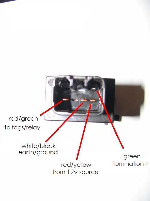
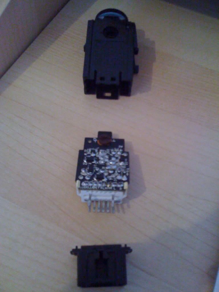
>Ok I have found out a bit more info on the UK 8 pin fog light switch.
Each pin connected to the PCB has the following printed next to the solder where the pins join the circuit board.
1 - L
2 - Illumination (+)
3 - B
4 - HR
5 - LH
6 - FS
7 - E
8 - Illumination (-)
I have no idea what 1,3,4,5,6,7 mean tho.
1 - L = to rear fog indicator light on dash, color = R
2 - ill + = tap into any ill source on dash
3 - B = from fuse ECU-B (so +), color = G-R
4 - HR = from HEAD relay (A2 side of the relay/coil) so that fog only operates when lights are ON, color = R-Y
5 - LH = to light control switch/ daytime running light relay pin "H" (sits on top of integration relay), color = R-B
6 - FS = from front fog light relay (A2 side of the relay/coil) , so if you don't have front fogs or relay -> earth to chassis ground, color = G-B
7 - E = other side of the dash indicator light, goes to junction block Nr 3, pin 3A, color = W-B
8 - ill - = earth to chassis ground or ill - anywhere in dash