Over 1M Posts • 84K Topics • 9K Authors

Selfmade Sequential Shift Light - 6G Celicas Forums

Topic #91125 10 posts Started by Hafkai
It´s not the most usefull thing but i just felt the urge to build something like this wink.gif .... the core of this little project is a Arduino Micro, a very small but capable microcontroller board. I´m not a fan of huge shift lights that go on all of a sudden so i tried to build a sequential shift light myself, it took me some time to get the Arduino to do anything without any programming knowledge but i somehow managed to make it work smile.gif

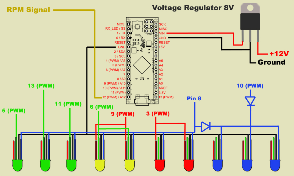
This is the outcome:

Arduino Micro Shift Light

Test setup


I used my mini DSO as signal generator, a wonderful little tool.


Really cool! Good job

2007 Impreza 2.5i - Daily1994 Camry - Sold1994 Celica - Sold :(Click hereto see my progress thread!
awesome

Mike W1996 Toyota Celica ST205 GT-FOURGT2860RS turbine, TiAL mvr44, JE 86.5φ piston, Clutchmasters FX400, APEX P-FC269awhp / 273ft-lbs
Would you awesome and show us how you made this work?

For Sale:OEM tail lights - make offer
This is basically how i made it, would have been a lot easier with normal LEDs but i wanted them all to be able to blink blue so i had to use RGB LEDs.
I put 1000-2000 Ohm resistors in front of every used LED pin, they were still way to bright but thanks to the PWM outputs its easy to dim them and to make any color as i did with the yellow stage.


And this is the code for the Arduino, not perfect, i still need to get some kind of rpm or frequency counter working, for now the code counts the time between the pulses:

>
QUOTE
>int rev = 12;
int ledGr1 = 5;
int ledGr2 = 13;
int ledGr3 = 11;
int ledG1 = 6;
int ledG2 = 9;
int ledRo = 3;
int ledBl = 10;
int ledAll = 8;
unsigned long duration;

void setup(){
Serial.begin(19200);
pinMode(8, OUTPUT);
pinMode(rev, INPUT);
}
void loop(){
Serial.print("Duration: ");
Serial.println(duration);
duration = pulseIn(rev, HIGH);

if (duration < 800 && duration > 100) {
digitalWrite(ledAll, HIGH);
delay(40);
digitalWrite(ledAll, LOW);
delay(40);
}
if (duration < 2800) analogWrite(ledGr1, 20);
if (duration > 2850 || duration < 800) analogWrite(ledGr1, 0);
if (duration < 2500) analogWrite(ledGr2, 20);
if (duration > 2550 || duration < 800) analogWrite(ledGr2, 0);
if (duration < 2300) analogWrite(ledGr3, 20);
if (duration > 2350 || duration < 800) analogWrite(ledGr3, 0);
if (duration < 2000) analogWrite(ledG1, 20);
if (duration > 2050 || duration < 800) analogWrite(ledG1, 0);
if (duration < 2000) analogWrite(ledG2, 60);
if (duration > 2050 || duration < 800) analogWrite(ledG2, 0);
if (duration < 1500) analogWrite(ledRo, 40);
if (duration > 1550 || duration < 800) analogWrite(ledRo, 0);
if (duration < 1100) analogWrite(ledBl, 20);
if (duration > 1150 || duration < 800) analogWrite(ledBl, 0);
delay(50);
}
It is really impressive, good work. I have a question, where to get the rpm signal?
Looks like I'm going to have to make one some day!

What was the overall cost of this?

Edit:
Never mind, just looked it up at Radioshack and it's only $30 for the board!

The only thing is, I would have to program it to use all the individual LED's and not have it jump to doubles, after the green, like you currently have it.
I wouldn't have the blues in there either. Probably just have 3 green, 2 yellows, 2 red, and no extra ones for blue, but have all them flash blue when it's at the set shift point.

This post has been edited by mkernz22: Nov 29, 2013 - 11:49 AM
>
QUOTE (angel_st @ Nov 29, 2013 - 5:02 PM) *
>It is really impressive, good work. I have a question, where to get the rpm signal?

I took the rpm signal from my EMS Motorsport ECU but you can take any signal that changes with rpm, ignition or injector signals should work. With the stock ignition system you can simply take the signal wire that feeds the tach.

>
QUOTE (mkernz22 @ Nov 29, 2013 - 5:32 PM) *
>The only thing is, I would have to program it to use all the individual LED's and not have it jump to doubles, after the green, like you currently have it.
I wouldn't have the blues in there either. Probably just have 3 green, 2 yellows, 2 red, and no extra ones for blue, but have all them flash blue when it's at the set shift point.

Should be no problem as long as you have enough output pins smile.gif
Hi,

Just wondering what spec diodes you used between the Arduino on Pin 8 and 10 (PWM) and the LEDs. Thinking of having a go at this myself but was wondering roughly what diodes I'll need to protect the board?

Thanks,

Sean