
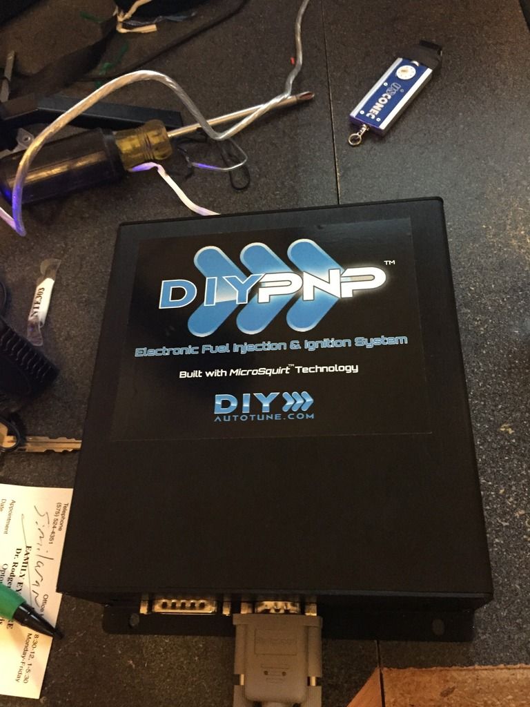
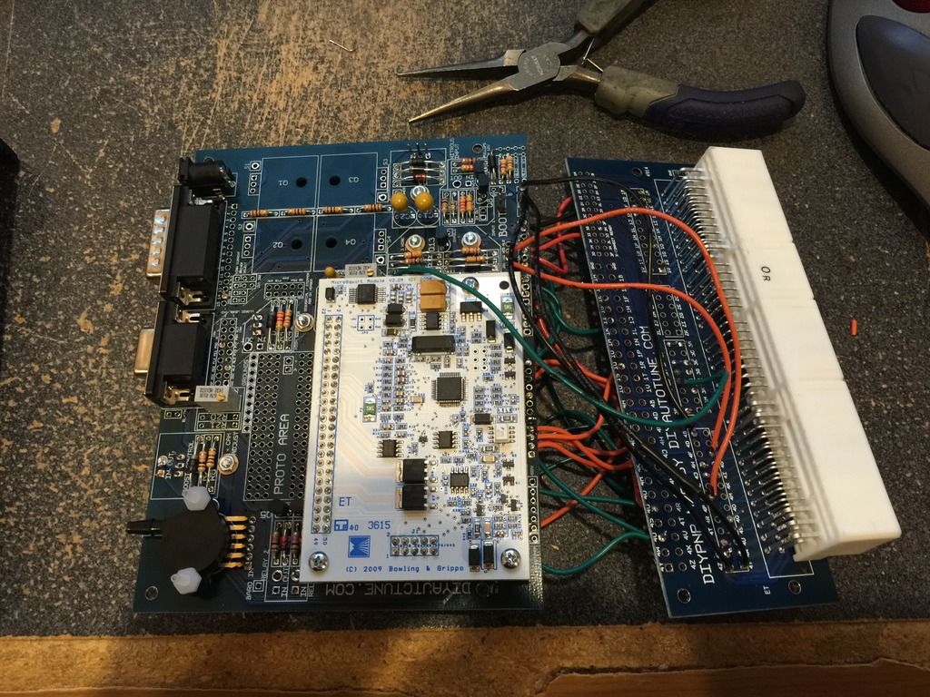
I have been having nothing but trouble with my AEM FIC on my 5sfte set up. I have a 97 Celica GT Convertible with a newly rebuilt engine and a 16G CT-26 turbo set up. The ECU is not working well with the signals the piggyback is feeding the stock ECU. Based on a couple of posts I have seen on 6gc.net, I broke down and bought a diypnp 76 pin standalone. The diypnp has all the features I am looking for and the price doesn't break the bank. I just finished soldering the main board and am about to start doing the harness jumpers. Can anyone provide and example for wiring the diypnp?
Building a diypnp - 6G Celicas Forums
Lagos is your main man for that. PM him
1995 GT::::Diffusing the Situationエキサイティングカーレーシングチーム!march2010 COTM:6GCfeature2014:january2015-2016-2018 COTM
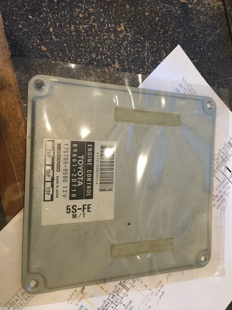
To start the diypnp project, I cracked open the factory ECU to get the pinout locations.
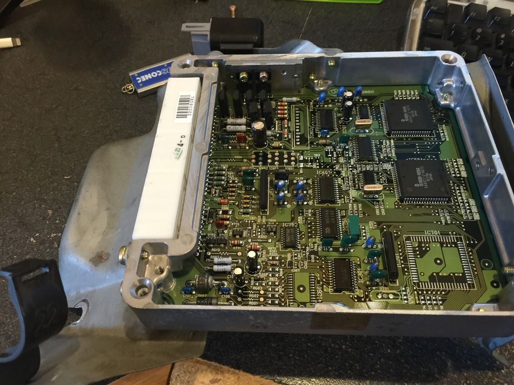
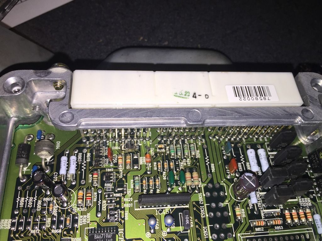
I created the following document to help me.
I am still working out what sensors need to be hooked up and how they need to be wired. My initial goal will be to get the car to start and get the timing right at idle. Then I can start added more sensors and get a drivable street tune. More to come.
This post has been edited by HardHead93: Dec 2, 2015 - 12:42 AM


I created the following document to help me.

I am still working out what sensors need to be hooked up and how they need to be wired. My initial goal will be to get the car to start and get the timing right at idle. Then I can start added more sensors and get a drivable street tune. More to come.
This post has been edited by HardHead93: Dec 2, 2015 - 12:42 AM
>
Now that I have the pinout locations I need to figure out how to wire them on the motherboard. It really sucks that so much of the factory functionality goes through the ECU. Functions like the back up light, A/C, headlights, defogger, and Cruise Control are all pinouts in the ECU. I think once I get the car running I will figure out how to run 12V power to them. I will also need to determine what are sensors for CEL and what actually control something on the car. This is going to take some time.
QUOTE (HardHead93 @ Nov 25, 2015 - 2:44 AM) 
>I have been having nothing but trouble with my AEM FIC on my 5sfte set up. I have a 97 Celica GT Convertible with a newly rebuilt engine and a 16G CT-26 turbo set up. The ECU is not working well with the signals the piggyback is feeding the stock ECU. Based on a couple of posts I have seen on 6gc.net, I broke down and bought a diypnp 76 pin standalone. The diypnp has all the features I am looking for and the price doesn't break the bank. I just finished soldering the main board and am about to start doing the harness jumpers. Can anyone provide and example for wiring the diypnp?
Now that I have the pinout locations I need to figure out how to wire them on the motherboard. It really sucks that so much of the factory functionality goes through the ECU. Functions like the back up light, A/C, headlights, defogger, and Cruise Control are all pinouts in the ECU. I think once I get the car running I will figure out how to run 12V power to them. I will also need to determine what are sensors for CEL and what actually control something on the car. This is going to take some time.
you most certainly need PIM. that is the MAP sensor. it is the main tuning sensor.
2001 Celica GT-S Turbo1997 Supra TT 6speed1997 Celica 3MZ/1MZ swap1990 Celica All-Trac
>
The DIYPMP has a built in 2.5 bar MAP sensor so it directs you to leave the factory one unplugged. The only other option is a 4 bar external unit but that still runs through a different pinout than the PIM.
This post has been edited by HardHead93: Nov 30, 2015 - 9:06 AM
QUOTE (Smaay @ Nov 29, 2015 - 8:45 PM)
>you most certainly need PIM. that is the MAP sensor. it is the main tuning sensor.
The DIYPMP has a built in 2.5 bar MAP sensor so it directs you to leave the factory one unplugged. The only other option is a 4 bar external unit but that still runs through a different pinout than the PIM.
This post has been edited by HardHead93: Nov 30, 2015 - 9:06 AM
W is CEL which is a switched ground to the negative side of the CEL bulb. what else?
Mike W1996 Toyota Celica ST205 GT-FOURGT2860RS turbine, TiAL mvr44, JE 86.5φ piston, Clutchmasters FX400, APEX P-FC269awhp / 273ft-lbs
ELS just leave it where it is, megasquirt should ignore it or do its own thing with it
in the tuning software you will assign functions onto the pins, so AC in and AC out will be able to be setup, cruise control should too
in the tuning software you will assign functions onto the pins, so AC in and AC out will be able to be setup, cruise control should too
Mike W1996 Toyota Celica ST205 GT-FOURGT2860RS turbine, TiAL mvr44, JE 86.5φ piston, Clutchmasters FX400, APEX P-FC269awhp / 273ft-lbs
>
The big one is the NE and G pinouts. I know they are cam and crank signals but all references say some thing different. Any ideas? Also where does the Tach signal get pulled from?
QUOTE (delusionz @ Nov 30, 2015 - 9:35 AM)
>W is CEL which is a switched ground to the negative side of the CEL bulb. what else?
The big one is the NE and G pinouts. I know they are cam and crank signals but all references say some thing different. Any ideas? Also where does the Tach signal get pulled from?
>
I figured out the A/C. So do I hook up power to the ELS or just leave it? Another question, there are 2 pinouts for ignition (IGS and IGT), but only one spot on the diypnp board what do I do with that?
QUOTE (delusionz @ Nov 30, 2015 - 9:41 AM)
>ELS just leave it where it is, megasquirt should ignore it or do its own thing with it
in the tuning software you will assign functions onto the pins, so AC in and AC out will be able to be setup, cruise control should too
in the tuning software you will assign functions onto the pins, so AC in and AC out will be able to be setup, cruise control should too
I figured out the A/C. So do I hook up power to the ELS or just leave it? Another question, there are 2 pinouts for ignition (IGS and IGT), but only one spot on the diypnp board what do I do with that?
>
You don't actually need to wire the majority of those to the ecu. Just stick with the basics of fuel and spark to get the engine running.
Stuff like the defogger input is just there to make the factory ecu idle up when there is an electrical load placed on it. The DIYPNP just monitors its own voltage and allows you to tune for that stuff without an extra input.
As far as AC, I didn't need to fully wire to the ecu to get it to work. All I did was supply an input signal so that the diypnp would know to initial AC idle up... but I would still wait to set that up once you have the car running.
QUOTE
>It really sucks that so much of the factory functionality goes through the ECU. Functions like the back up light, A/C, headlights, defogger, and Cruise Control are all pinouts in the ECU. I think once I get the car running I will figure out how to run 12V power to them. I will also need to determine what are sensors for CEL and what actually control something on the car. This is going to take some time.
You don't actually need to wire the majority of those to the ecu. Just stick with the basics of fuel and spark to get the engine running.
Stuff like the defogger input is just there to make the factory ecu idle up when there is an electrical load placed on it. The DIYPNP just monitors its own voltage and allows you to tune for that stuff without an extra input.
As far as AC, I didn't need to fully wire to the ecu to get it to work. All I did was supply an input signal so that the diypnp would know to initial AC idle up... but I would still wait to set that up once you have the car running.
15PSI - 30MPG - Megasquirt Tuned
>
I just heard back from diypnp.com on the question above.
NE=crankshaft
G=camshaft
Just my luck, I wired them the opposite.
QUOTE (HardHead93 @ Nov 30, 2015 - 4:09 PM)
>>
The big one is the NE and G pinouts. I know they are cam and crank signals but all references say some thing different. Any ideas? Also where does the Tach signal get pulled from?
QUOTE (delusionz @ Nov 30, 2015 - 9:35 AM)
>W is CEL which is a switched ground to the negative side of the CEL bulb. what else?
The big one is the NE and G pinouts. I know they are cam and crank signals but all references say some thing different. Any ideas? Also where does the Tach signal get pulled from?
I just heard back from diypnp.com on the question above.
NE=crankshaft
G=camshaft
Just my luck, I wired them the opposite.
>
All done with the wiring and firmware is loaded. What ignition settings do I need? I have a 97 5sfe, California ECU, and distributor with a separate crank sensor (I replaced it when I did the engine rebuild). Also any tips on building a basic tune for a 16G CT26 turbo with 460cc injectors?
Injection Settings
Spark Mode: ?
Trigger Angle: ?
Main/Return: ?
Odd fire Angle: ?
GM HEI/DIS: ?
Use Cam Signal: ?
Ignition Input Capture: ?
Spark Output: ?
Number of Coils: ?
Dwell type: ?
Cranking Dwell: ?
Cranking Advance: ?
Maximum Dwell: ?
Maximum Spark Duration: ?
Trigger wheel arrangement: ?
Trigger wheel teeth: ?
Missing teeth: ?
Tooth #1 angle: ?
Wheel speed: ?
Second trigger active on
and every rotation of: ?
QUOTE (lagos @ Dec 1, 2015 - 11:08 AM)
>>
You don't actually need to wire the majority of those to the ecu. Just stick with the basics of fuel and spark to get the engine running.
Stuff like the defogger input is just there to make the factory ecu idle up when there is an electrical load placed on it. The DIYPNP just monitors its own voltage and allows you to tune for that stuff without an extra input.
As far as AC, I didn't need to fully wire to the ecu to get it to work. All I did was supply an input signal so that the diypnp would know to initial AC idle up... but I would still wait to set that up once you have the car running.
QUOTE
>It really sucks that so much of the factory functionality goes through the ECU. Functions like the back up light, A/C, headlights, defogger, and Cruise Control are all pinouts in the ECU. I think once I get the car running I will figure out how to run 12V power to them. I will also need to determine what are sensors for CEL and what actually control something on the car. This is going to take some time.
You don't actually need to wire the majority of those to the ecu. Just stick with the basics of fuel and spark to get the engine running.
Stuff like the defogger input is just there to make the factory ecu idle up when there is an electrical load placed on it. The DIYPNP just monitors its own voltage and allows you to tune for that stuff without an extra input.
As far as AC, I didn't need to fully wire to the ecu to get it to work. All I did was supply an input signal so that the diypnp would know to initial AC idle up... but I would still wait to set that up once you have the car running.
All done with the wiring and firmware is loaded. What ignition settings do I need? I have a 97 5sfe, California ECU, and distributor with a separate crank sensor (I replaced it when I did the engine rebuild). Also any tips on building a basic tune for a 16G CT26 turbo with 460cc injectors?
Injection Settings
Spark Mode: ?
Trigger Angle: ?
Main/Return: ?
Odd fire Angle: ?
GM HEI/DIS: ?
Use Cam Signal: ?
Ignition Input Capture: ?
Spark Output: ?
Number of Coils: ?
Dwell type: ?
Cranking Dwell: ?
Cranking Advance: ?
Maximum Dwell: ?
Maximum Spark Duration: ?
Trigger wheel arrangement: ?
Trigger wheel teeth: ?
Missing teeth: ?
Tooth #1 angle: ?
Wheel speed: ?
Second trigger active on
and every rotation of: ?


>
So I have calibrated all the sensors and set up the fuel map and the car will not start. It does turnover but will not start. What am I doing wrong? I have the following ignition settings.
Spark Mode: Toothed Wheel
Trigger Angle: 4.00
Main/Return: 50.0
Odd fire Angle: 90
GM HEI/DIS: Off
Use Cam Signal: On
Ignition Input Capture: Falling Edge
Spark Output: Going High
Number of Coils: Wasted Spark
Dwell type: Standard Dwell
Cranking Dwell: 7.5
Cranking Advance: 10
Maximum Dwell: ?
Maximum Spark Duration: ?
Trigger wheel arrangement: Single Wheel with Missing Tooth
Trigger wheel teeth: 36
Missing teeth: 1
Tooth #1 angle: 0
Wheel speed: Crank Wheel
Second trigger active on
and every rotation of: Rising Edge
QUOTE (lagos @ Dec 1, 2015 - 12:08 PM)
>>
You don't actually need to wire the majority of those to the ecu. Just stick with the basics of fuel and spark to get the engine running.
Stuff like the defogger input is just there to make the factory ecu idle up when there is an electrical load placed on it. The DIYPNP just monitors its own voltage and allows you to tune for that stuff without an extra input.
As far as AC, I didn't need to fully wire to the ecu to get it to work. All I did was supply an input signal so that the diypnp would know to initial AC idle up... but I would still wait to set that up once you have the car running.
QUOTE
>It really sucks that so much of the factory functionality goes through the ECU. Functions like the back up light, A/C, headlights, defogger, and Cruise Control are all pinouts in the ECU. I think once I get the car running I will figure out how to run 12V power to them. I will also need to determine what are sensors for CEL and what actually control something on the car. This is going to take some time.
You don't actually need to wire the majority of those to the ecu. Just stick with the basics of fuel and spark to get the engine running.
Stuff like the defogger input is just there to make the factory ecu idle up when there is an electrical load placed on it. The DIYPNP just monitors its own voltage and allows you to tune for that stuff without an extra input.
As far as AC, I didn't need to fully wire to the ecu to get it to work. All I did was supply an input signal so that the diypnp would know to initial AC idle up... but I would still wait to set that up once you have the car running.
So I have calibrated all the sensors and set up the fuel map and the car will not start. It does turnover but will not start.
What am I doing wrong? I have the following ignition settings.Spark Mode: Toothed Wheel
Trigger Angle: 4.00
Main/Return: 50.0
Odd fire Angle: 90
GM HEI/DIS: Off
Use Cam Signal: On
Ignition Input Capture: Falling Edge
Spark Output: Going High
Number of Coils: Wasted Spark
Dwell type: Standard Dwell
Cranking Dwell: 7.5
Cranking Advance: 10
Maximum Dwell: ?
Maximum Spark Duration: ?
Trigger wheel arrangement: Single Wheel with Missing Tooth
Trigger wheel teeth: 36
Missing teeth: 1
Tooth #1 angle: 0
Wheel speed: Crank Wheel
Second trigger active on
and every rotation of: Rising Edge
I still can't seem to figure it out. The car turns over but will not start. Occasionally it will sputter and almost start so I know it is getting fuel. I put the stock ECU back in with the piggyback and the car started right up. I wonder if it has something to do with the adjustable pull up resistor on the board for the cam and crank sensors. I has the same issue with the AEM FIC piggyback when I put too big of a resistor for the mod to clean up the cam and crank signals. I have the crank sensor running through the LM1815 circuit for a cleaner signal and still nothing. I will see if I can adjust the pull up resistance.
This post has been edited by HardHead93: Dec 7, 2015 - 9:10 AM
This post has been edited by HardHead93: Dec 7, 2015 - 9:10 AM
Sorry for the lack of help, been really busy.
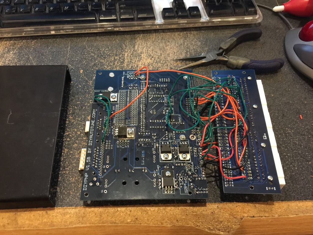
I see that you don't have the pull down resistor installed in R21. This is key to getting a cam/crank signal from a Toyota distributor.
The DIYPNP kit supplies you with an extra resistor (I think its a 50kohm?). For my build, I went with a 33kohm as I heard that's what the diyautotune guys settled with for the built 3sgte mspnp units. There is also an adjustable trim pot supplied with the kit that you can try, but I would start out with the fixed resistor. Actually, just noticed that you have the trim pot in there, so you can try adjusting that.
To verify that you are getting cam/crank signals in the Diagnostics & High Speed Loggers section of Turner Studio. Just click to start the logger and crank the car. You should be seeing your cam/crank signals. Adjust the trim pot until you start getting a reading.
PM me your email address, I will send you my excel spread sheet that I made for my car, as well as my current tune. My engine is a 3sgte, but all the settings should be very similar to the 5sfe to get it to start. Just make sure you setup/scale your injectors so that you are not flooding the engine.
This post has been edited by lagos: Dec 8, 2015 - 12:28 PM
15PSI - 30MPG - Megasquirt Tuned
>
Some of these settings are also different than what Im using in my tune.
A big one that stands out is that you are setup for waste spark, and mine is setup for single coil.
Also your Tooth 1 angle is at 0, and mine is a 37. Tooth 1 angle is how you set your base ignition timing, so having that at zero would cause some issues. I think that working from my tune map will help you clear up some of these settings.
Also for the cam signal, we have G1 and G2. You can use either one. For my distributor, I had trouble getting a signal from G1 so I switched to G2. Switching these might also affect your tooth 1 angle. The angle I posted is what I'm using on G2.
This post has been edited by lagos: Dec 8, 2015 - 12:42 PM
QUOTE
>Spark Mode: Toothed Wheel
Trigger Angle: 4.00
Main/Return: 50.0
Odd fire Angle: 90
GM HEI/DIS: Off
Use Cam Signal: On
Ignition Input Capture: Falling Edge
Spark Output: Going High
Number of Coils: Wasted Spark
Dwell type: Standard Dwell
Cranking Dwell: 7.5
Cranking Advance: 10
Maximum Dwell: ?
Maximum Spark Duration: ?
Trigger wheel arrangement: Single Wheel with Missing Tooth
Trigger wheel teeth: 36
Missing teeth: 1
Tooth #1 angle: 0
Wheel speed: Crank Wheel
Second trigger active on
and every rotation of: Rising Edge
Some of these settings are also different than what Im using in my tune.
A big one that stands out is that you are setup for waste spark, and mine is setup for single coil.
Also your Tooth 1 angle is at 0, and mine is a 37. Tooth 1 angle is how you set your base ignition timing, so having that at zero would cause some issues. I think that working from my tune map will help you clear up some of these settings.
Also for the cam signal, we have G1 and G2. You can use either one. For my distributor, I had trouble getting a signal from G1 so I switched to G2. Switching these might also affect your tooth 1 angle. The angle I posted is what I'm using on G2.
This post has been edited by lagos: Dec 8, 2015 - 12:42 PM
15PSI - 30MPG - Megasquirt Tuned
>
Yeah, we don't have a wasted spark setup on the 3sgte.
One engine I can think of that does run that is the 1mzfe on certain years of the engine.
Basically, there's one coil for each cylinder on the front bank, which then has a wire running to a corresponding cylinder on the rear bank.
QUOTE (lagos @ Dec 8, 2015 - 12:25 PM)
>>
Some of these settings are also different than what Im using in my tune.
A big one that stands out is that you are setup for waste spark, and mine is setup for single coil.
Also your Tooth 1 angle is at 0, and mine is a 37. Tooth 1 angle is how you set your base ignition timing, so having that at zero would cause some issues. I think that working from my tune map will help you clear up some of these settings.
Also for the cam signal, we have G1 and G2. You can use either one. For my distributor, I had trouble getting a signal from G1 so I switched to G2. Switching these might also affect your tooth 1 angle. The angle I posted is what I'm using on G2.
QUOTE
>Spark Mode: Toothed Wheel
Trigger Angle: 4.00
Main/Return: 50.0
Odd fire Angle: 90
GM HEI/DIS: Off
Use Cam Signal: On
Ignition Input Capture: Falling Edge
Spark Output: Going High
Number of Coils: Wasted Spark
Dwell type: Standard Dwell
Cranking Dwell: 7.5
Cranking Advance: 10
Maximum Dwell: ?
Maximum Spark Duration: ?
Trigger wheel arrangement: Single Wheel with Missing Tooth
Trigger wheel teeth: 36
Missing teeth: 1
Tooth #1 angle: 0
Wheel speed: Crank Wheel
Second trigger active on
and every rotation of: Rising Edge
Trigger Angle: 4.00
Main/Return: 50.0
Odd fire Angle: 90
GM HEI/DIS: Off
Use Cam Signal: On
Ignition Input Capture: Falling Edge
Spark Output: Going High
Number of Coils: Wasted Spark
Dwell type: Standard Dwell
Cranking Dwell: 7.5
Cranking Advance: 10
Maximum Dwell: ?
Maximum Spark Duration: ?
Trigger wheel arrangement: Single Wheel with Missing Tooth
Trigger wheel teeth: 36
Missing teeth: 1
Tooth #1 angle: 0
Wheel speed: Crank Wheel
Second trigger active on
and every rotation of: Rising Edge
Some of these settings are also different than what Im using in my tune.
A big one that stands out is that you are setup for waste spark, and mine is setup for single coil.
Also your Tooth 1 angle is at 0, and mine is a 37. Tooth 1 angle is how you set your base ignition timing, so having that at zero would cause some issues. I think that working from my tune map will help you clear up some of these settings.
Also for the cam signal, we have G1 and G2. You can use either one. For my distributor, I had trouble getting a signal from G1 so I switched to G2. Switching these might also affect your tooth 1 angle. The angle I posted is what I'm using on G2.
Yeah, we don't have a wasted spark setup on the 3sgte.
One engine I can think of that does run that is the 1mzfe on certain years of the engine.
Basically, there's one coil for each cylinder on the front bank, which then has a wire running to a corresponding cylinder on the rear bank.
Any progress on this project?
15PSI - 30MPG - Megasquirt Tuned
Also, I just found a very cool time lapse video of someone building a DIYPNP.
https://www.youtube.com/watch?v=n9OTCb-aS5k
https://www.youtube.com/watch?v=n9OTCb-aS5k
15PSI - 30MPG - Megasquirt Tuned
>
I had some problems with the oil feed line to the turbo so I had to fix that. Now I am back on working with the diypnp. I can get the car to start but I cannot keep it idling without putting my foot on the gas. What exactly am I supposed to see on the high speed logger because the RPM signal is all over the place?
This post has been edited by HardHead93: Feb 7, 2016 - 11:46 PM
QUOTE (lagos @ Jan 29, 2016 - 12:49 PM)
>Any progress on this project?
I had some problems with the oil feed line to the turbo so I had to fix that. Now I am back on working with the diypnp. I can get the car to start but I cannot keep it idling without putting my foot on the gas. What exactly am I supposed to see on the high speed logger because the RPM signal is all over the place?
This post has been edited by HardHead93: Feb 7, 2016 - 11:46 PM
Got the DIYPNP running exactly like I want it to but I am still having trouble figuring out the AC idle up. I have been working with the guys over at DIYAutoTune and I am still having problems. I took voltage measurements off the AC pinouts on the ECU and came up with the following:
With the A/C off:
AC1: 0.15V
ACT: 0.15V
ATS: 0.00V
With the A/C on:
AC1: 0.29V
ACT: 5.55V
ATS: 0.00V
The zero voltage on the ATS pin make sense because when I looked at the factory harness there was no wire connected to it.
The guys at at DIYAutoTune told me to do the following:
"Try wiring ACT to the nitrous input IN and the OUT to an unused input (FLEX or PE1), and use this for A/C idle up."
When I did that the AC compressor clutch would not kick on. I really want to figure this out because when I run the AC the additional load causes the car to sometimes stall at idle. Any ideas?
Glad you were able to get the unit working!
Here is what I did for AC idle up.
I disconnected all AC1, ACT, ATS connections. With nothing hooked up to the ecu, the ac compressor would come on just fine.
Next, I looked at the vehicle wiring diagram to determine the wire that ground switches the ac compressor relay in the passengers side fuse box.
I cut that wire and ran the ground signal into the Flex pin. Then I connected the PA0 output to control the ac relay.
I believe the in order to use the PA0 output, you have to run it into the in port of relay1,relay2 or relay3 of the DIYPNP circuit board. Just double check this in the assembly documentation.
Does the car stall at idle or deceleration?
15PSI - 30MPG - Megasquirt Tuned
>
You can also try sending 5v to AC1 to see if the compressor comes on.
QUOTE
>With the A/C on:
AC1: 0.29V
ACT: 5.55V
ATS: 0.00V
AC1: 0.29V
ACT: 5.55V
ATS: 0.00V
You can also try sending 5v to AC1 to see if the compressor comes on.
15PSI - 30MPG - Megasquirt Tuned
>
Yes, when the AC is on the moment I push the clutch in the car stalls. I sent an e-mail to DIYAutoTune and got the following response back:
"It looks like the magnetic clutch is triggered by the "MCG" pin on the ECU. You'll want to configure the DIYPNP to use an on/off output on that pin, set as the "A/C idle up output" pin."
The only other AC pin on the ECU for my car is the AC1. Is that the AC idle up signal? The ACT is used for cutting the AC when the car is under high load which explains why the AC stops working when I connect to that pinout.
>
Do you mean wire the PAO to the AC1 pinout and set TunerStudio for 5V signal?
This post has been edited by HardHead93: Aug 9, 2016 - 11:07 PM
QUOTE (lagos @ Aug 9, 2016 - 1:21 PM)
>Glad you were able to get the unit working!
Here is what I did for AC idle up.
I disconnected all AC1, ACT, ATS connections. With nothing hooked up to the ecu, the ac compressor would come on just fine.
Next, I looked at the vehicle wiring diagram to determine the wire that ground switches the ac compressor relay in the passengers side fuse box.
I cut that wire and ran the ground signal into the Flex pin. Then I connected the PA0 output to control the ac relay.
I believe the in order to use the PA0 output, you have to run it into the in port of relay1,relay2 or relay3 of the DIYPNP circuit board. Just double check this in the assembly documentation.
Does the car stall at idle or deceleration?
Yes, when the AC is on the moment I push the clutch in the car stalls. I sent an e-mail to DIYAutoTune and got the following response back:
"It looks like the magnetic clutch is triggered by the "MCG" pin on the ECU. You'll want to configure the DIYPNP to use an on/off output on that pin, set as the "A/C idle up output" pin."
The only other AC pin on the ECU for my car is the AC1. Is that the AC idle up signal? The ACT is used for cutting the AC when the car is under high load which explains why the AC stops working when I connect to that pinout.
>
QUOTE (lagos @ Aug 9, 2016 - 2:44 PM)
>>
You can also try sending 5v to AC1 to see if the compressor comes on.
QUOTE
>With the A/C on:
AC1: 0.29V
ACT: 5.55V
ATS: 0.00V
AC1: 0.29V
ACT: 5.55V
ATS: 0.00V
You can also try sending 5v to AC1 to see if the compressor comes on.
Do you mean wire the PAO to the AC1 pinout and set TunerStudio for 5V signal?
This post has been edited by HardHead93: Aug 9, 2016 - 11:07 PM
>
When driving or when the car is at idle?
>
I don't think there is an MCG pin on the ecu?
>
Yes but in order to use PA0 for anything, you need to run it through a transistor first (one of the relays on the circuit board).
See the programable on/off section here:
https://www.diyautotune.com/support/tech/ha...On/Off_Outputs_
I would also check this functionality with a multimeter to make sure that it changes to a voltage switching circuit.
Remember that if all of this fails, you can just intercept the ground switching wire that goes to the AC relay like I did.
QUOTE
>Yes, when the AC is on the moment I push the clutch in the car stalls
When driving or when the car is at idle?
>
QUOTE
>"It looks like the magnetic clutch is triggered by the "MCG" pin on the ECU. You'll want to configure the DIYPNP to use an on/off output on that pin, set as the "A/C idle up output" pin."
I don't think there is an MCG pin on the ecu?
>
QUOTE
>Do you mean wire the PAO to the AC1 pinout and set TunerStudio for 5V signal?
Yes but in order to use PA0 for anything, you need to run it through a transistor first (one of the relays on the circuit board).
See the programable on/off section here:
https://www.diyautotune.com/support/tech/ha...On/Off_Outputs_
I would also check this functionality with a multimeter to make sure that it changes to a voltage switching circuit.
Remember that if all of this fails, you can just intercept the ground switching wire that goes to the AC relay like I did.
15PSI - 30MPG - Megasquirt Tuned
>
The car stalls when I take the load off the engine for too long, so yes it happens when I idle or if I chose to coast not in gear. This only happens when I have the AC running. If I blip the throttle before the RPMs get to low I can sometimes stop the car from stalling and it will catch itself and continue to idle, although the idle is really weak.
QUOTE (lagos @ Aug 10, 2016 - 1:08 PM)
>>
When driving or when the car is at idle?
>
I don't think there is an MCG pin on the ecu?
>
Yes but in order to use PA0 for anything, you need to run it through a transistor first (one of the relays on the circuit board).
See the programable on/off section here:
https://www.diyautotune.com/support/tech/ha...On/Off_Outputs_
I would also check this functionality with a multimeter to make sure that it changes to a voltage switching circuit.
Remember that if all of this fails, you can just intercept the ground switching wire that goes to the AC relay like I did.
QUOTE
>Yes, when the AC is on the moment I push the clutch in the car stalls
When driving or when the car is at idle?
>
QUOTE
>"It looks like the magnetic clutch is triggered by the "MCG" pin on the ECU. You'll want to configure the DIYPNP to use an on/off output on that pin, set as the "A/C idle up output" pin."
I don't think there is an MCG pin on the ecu?
>
QUOTE
>Do you mean wire the PAO to the AC1 pinout and set TunerStudio for 5V signal?
Yes but in order to use PA0 for anything, you need to run it through a transistor first (one of the relays on the circuit board).
See the programable on/off section here:
https://www.diyautotune.com/support/tech/ha...On/Off_Outputs_
I would also check this functionality with a multimeter to make sure that it changes to a voltage switching circuit.
Remember that if all of this fails, you can just intercept the ground switching wire that goes to the AC relay like I did.
The car stalls when I take the load off the engine for too long, so yes it happens when I idle or if I chose to coast not in gear. This only happens when I have the AC running. If I blip the throttle before the RPMs get to low I can sometimes stop the car from stalling and it will catch itself and continue to idle, although the idle is really weak.
Send me your MSQ file. lagos3sgte@gmail.com
AC idle up helps the engine get a smoother transition when the ac comes on, but its not always what is responsible for stalling issues like that.
AC idle up helps the engine get a smoother transition when the ac comes on, but its not always what is responsible for stalling issues like that.
15PSI - 30MPG - Megasquirt Tuned
>
I just installed some WebCams in the engine, I will send you the file once I do a couple pulls this weekend with the new camshafts and get AutoTune to adjust the fuel table.
QUOTE (lagos @ Aug 10, 2016 - 4:55 PM)
>Send me your MSQ file. lagos3sgte@gmail.com
AC idle up helps the engine get a smoother transition when the ac comes on, but its not always what is responsible for stalling issues like that.
AC idle up helps the engine get a smoother transition when the ac comes on, but its not always what is responsible for stalling issues like that.
I just installed some WebCams in the engine, I will send you the file once I do a couple pulls this weekend with the new camshafts and get AutoTune to adjust the fuel table.
>
Your stalling is probably cause by an overrun fuel cut setting or some oddness in your fuel table, hence why I asked for the file. The WOT pulls don't matter for this.
QUOTE (HardHead93 @ Aug 11, 2016 - 10:03 PM)
>>
I just installed some WebCams in the engine, I will send you the file once I do a couple pulls this weekend with the new camshafts and get AutoTune to adjust the fuel table.
QUOTE (lagos @ Aug 10, 2016 - 4:55 PM)
>Send me your MSQ file. lagos3sgte@gmail.com
AC idle up helps the engine get a smoother transition when the ac comes on, but its not always what is responsible for stalling issues like that.
AC idle up helps the engine get a smoother transition when the ac comes on, but its not always what is responsible for stalling issues like that.
I just installed some WebCams in the engine, I will send you the file once I do a couple pulls this weekend with the new camshafts and get AutoTune to adjust the fuel table.
Your stalling is probably cause by an overrun fuel cut setting or some oddness in your fuel table, hence why I asked for the file. The WOT pulls don't matter for this.
15PSI - 30MPG - Megasquirt Tuned