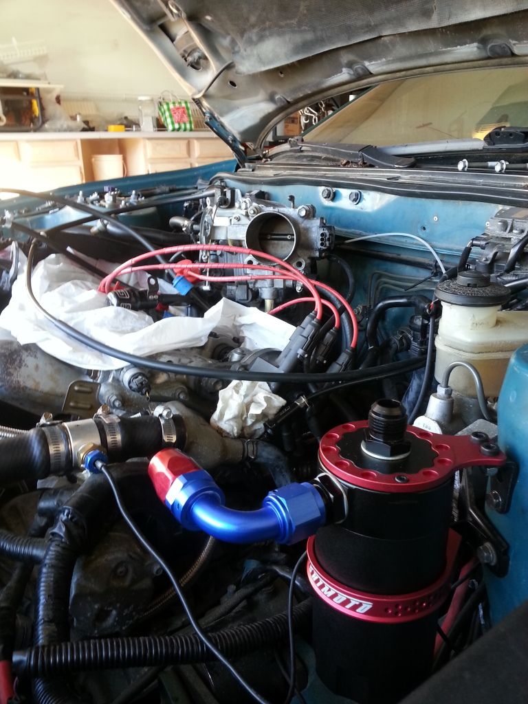
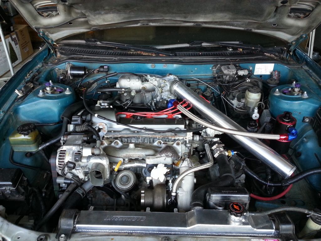
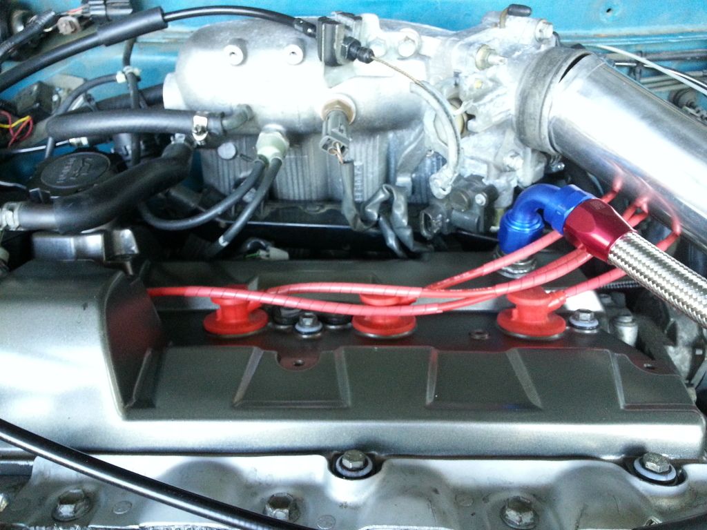
This afternoon I started working on the preliminary wiring to make the 4th gen throttle position sensor work with the 3rd gen computer. There are a few things that are involved. This information has been kind of a pain for me to get access to, and there aren't many sources out there that exist any more for a sort of "how-to"
So let's begin.
Disclaimer: Do not in any way shape or form assume that the colors that I used for my wiring are the same as the factory wiring. I used what I had, and will need to solder them to the correct colors coming from the factory harness.
There are also many different ways to screw in a light bulb. So what works for me might not work for you.
Lastly, if you screw up your car. It is NOT my fault. Again, this is a guide that works for me, and what works for me may not work for you. The most important thing is to know your limitations. If wiring isn't your thing, then don't do it.
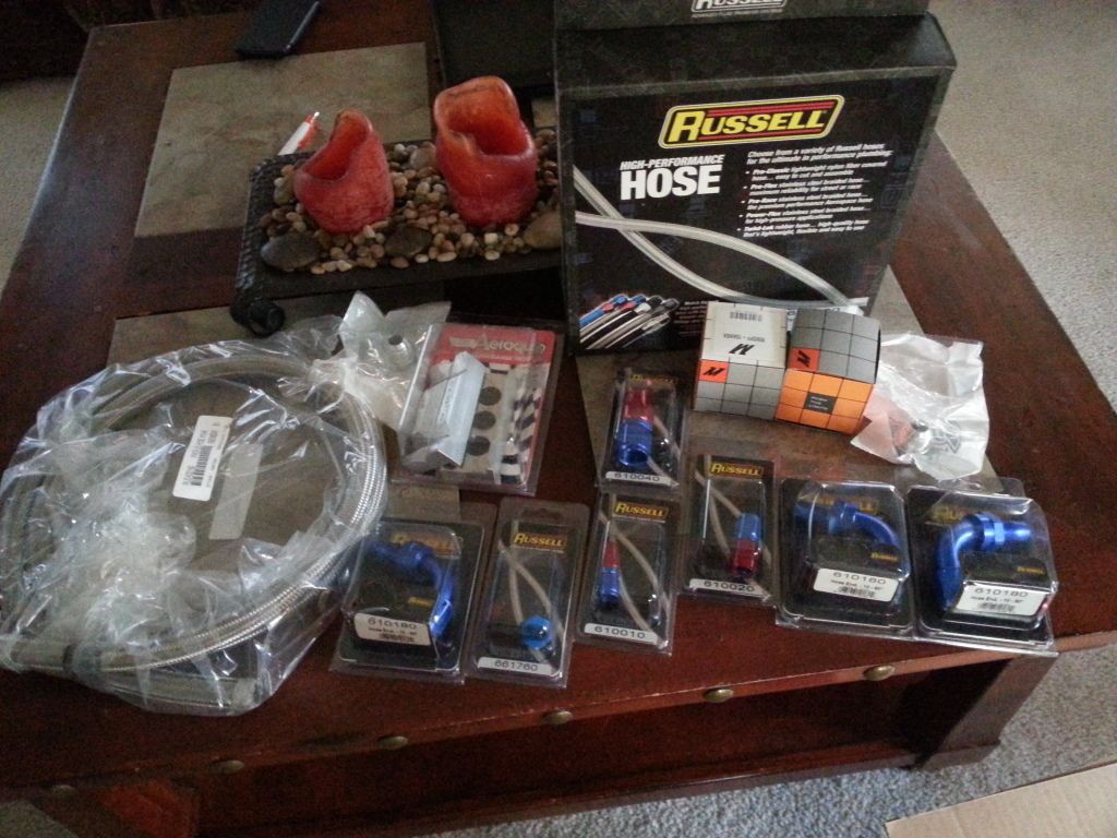
Things you will need:
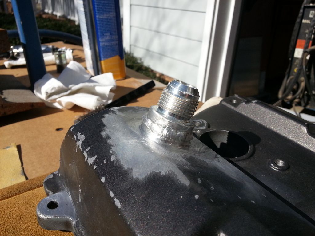
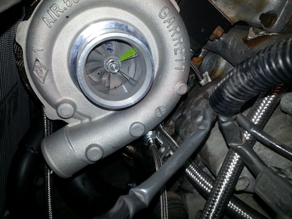
4th Gen manifold/throttle body
1zz tpms connector
spare wiring
wire cutters
crimps
tape
heat shrink
solder
soldering iron
assorted electrical connectors (I used spade clips)
Nitrous WOT switch
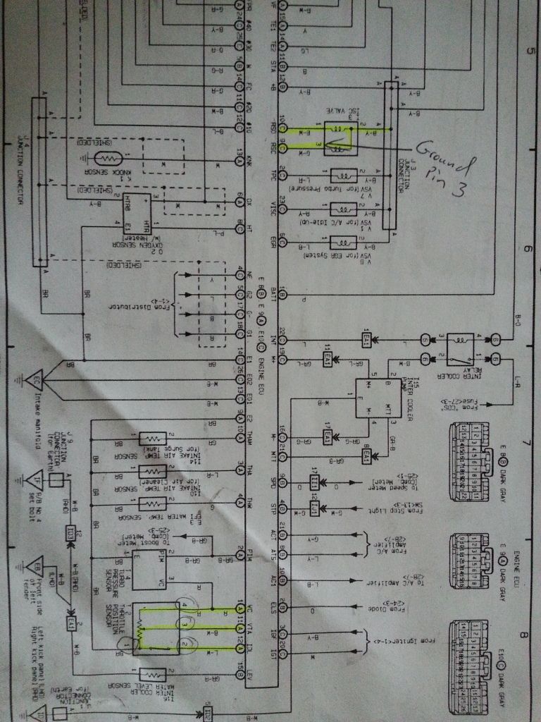
In this picture you can see that I have highlighted the circuits that need manipulation to work with the 3rd Gen ECM. This diagram belongs to a ST215 Caldina (Gen 4)
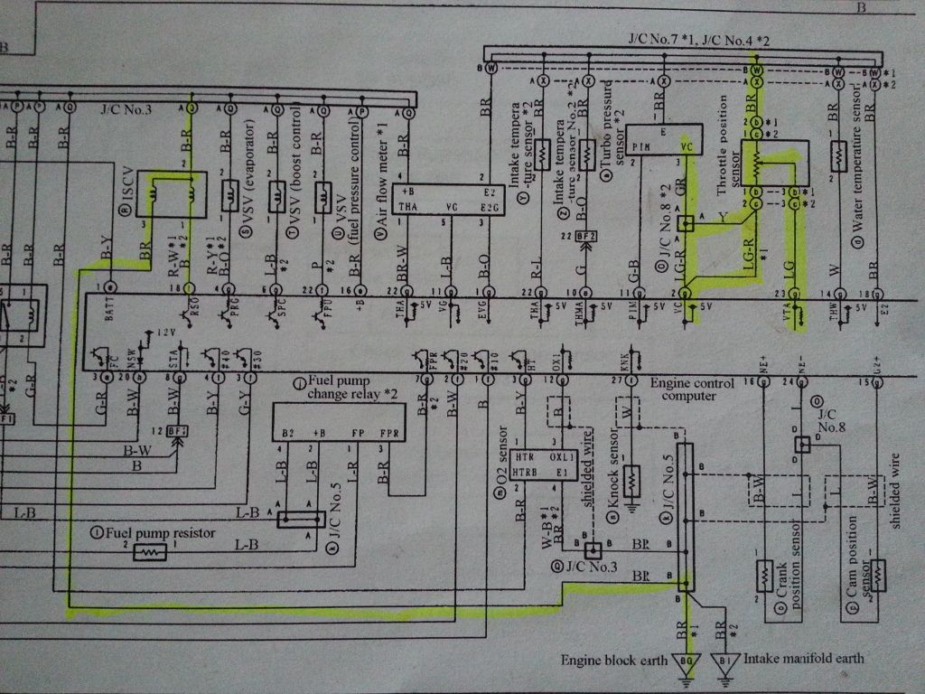
While they are fairly similar you can see differences in the circuit. This diagram belongs to an ST205 (3rd Gen)
Please try to ignore my notes on the diagram. I will get into the wiring for the IACV later, but as you can see it's really easy to adapt the 4th Gen IACV.

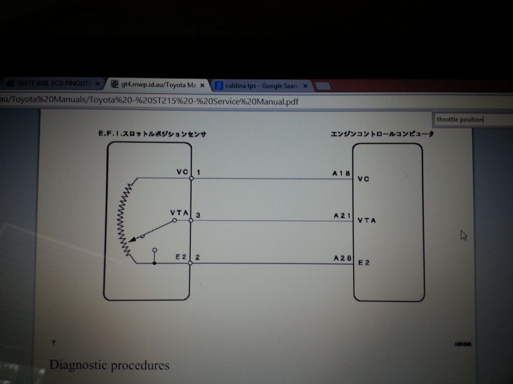
This diagram shows the 3rd Gen Throttle Position Sensor if you were looking directly at the pinouts with the harness un-plugged.

This image shows how the 3rd Gen sensor works. You can see in the image that when the throttle shuts, that E2 and IDL will touch, which tells the ECM to idle.
This image shows a diagram of the 4th Gen Throttle Position Sensor. Notice how IDL is missing from the 4th gen sensor. There is also no IDL pinout at the 4th gen ECM.

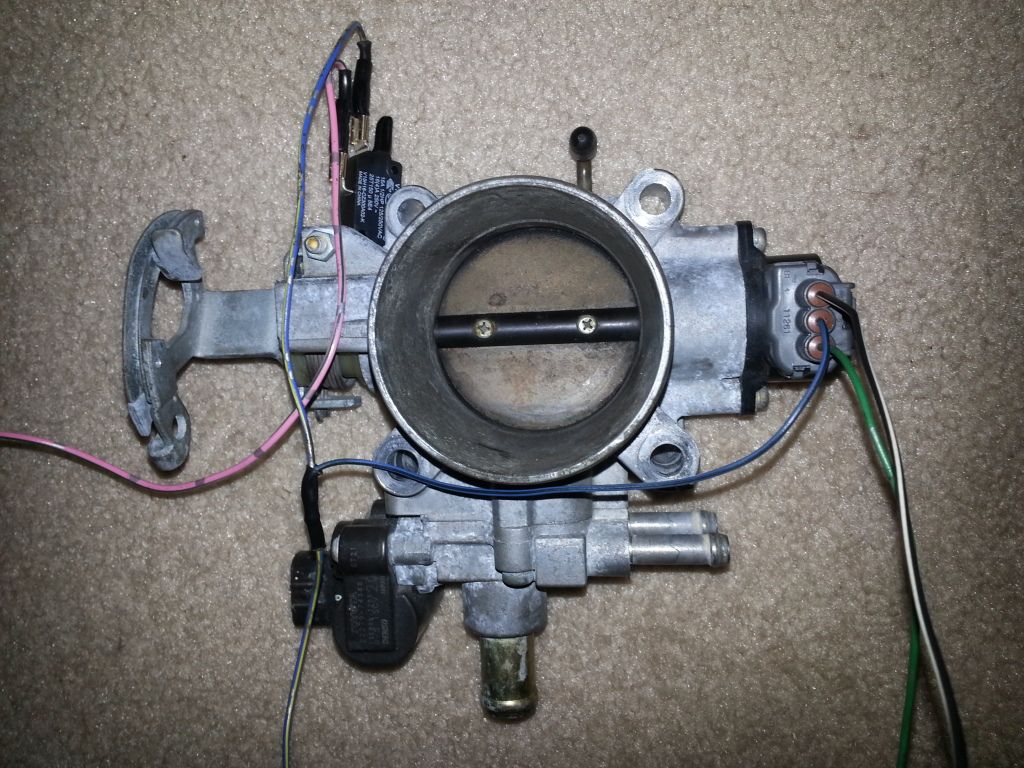
This is an image looking into the harness for the 4th Gen Throttle position sensor. I know it doesn't say it here, but leg three goes to VTA
VC AND ETA NEED TO BE SWITCHED! LEAVING IT LIKE IT IS WILL RESULT IN FAILURE!
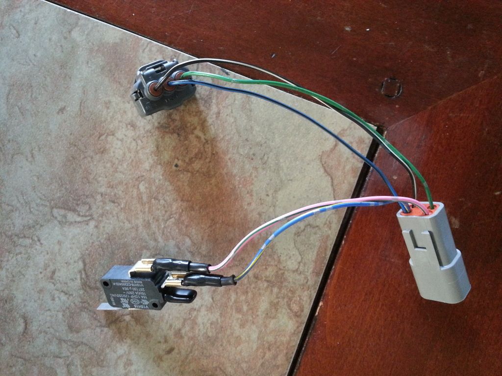
And here it what I have done. I left the wires bare to show how it works, but will cover the wiring with split loom, and clean it up before instal.
At the top left you can see the Nitrous WOT switch. This switch is key to performing the duties of the IDL function that the 4th gen sensor is devoid of.
On a 3rd gen 3sgte the vehicle must be switched into idle mode when your foot is not on the accelerator. The tab on this nitrous WOT switch is engaged when the
throttle stop on the throttle body closes. Meaning when the throttle shuts it presses the switch down, which completes a circuit. This information is then sent to the 3rd gen ECM on the IDL pinout to tell the vehicle to idle.
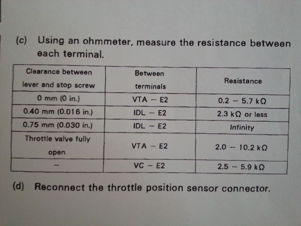
So in my last picture the top black wire on the TPS connector is VTA, the blue is VC, and the green is E2. I will connect these three wires directly to the same wires used for these exact functions on my factory 3rd Gen Harness. Meaning, I will solder the black wire to the black wire on the 3rd gen harness, the blue wire to the brown wire on the third gen harness, and the green wire to the red wire on the 3rd gen harness. From the 3rd gen harness I will be left with one remaining wire, that according to the diagram is Blue and White. This wire will be soldered to the pink wire coming off of my Nitrous WOT switch. You may have also noticed that I linked the blue wire from the tps to the blue wire on the WOT switch. As mentioned earlier "idle" occurs when E2 and IDL touch, BUT IN THIS CASE WILL OCCUR WHEN VC AND IDLE TOUCH. Hence when my WOT switch closes the VC and IDLE will complete the circuit. I'm going to make a bracket that holds my nitrous WOT switch. One things that must be considered is the activation points of the Nitrous WOT switch. This diagram below shows the tolerances that must be taken for the introduction of "idle" to occur at the right position of the throttle plate. I will have to make these adjustments after I get everything running, but wanted to make sure that I included this image for anyone else trying to attempt the same thing.
 This post has been edited by bsamps4: Feb 23, 2015 - 11:43 AM